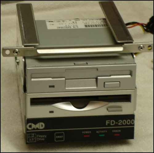
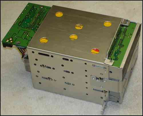
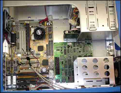
This is where we left off in the last update. Alan decided he would like a different look for the controller half of the
FD 2000.
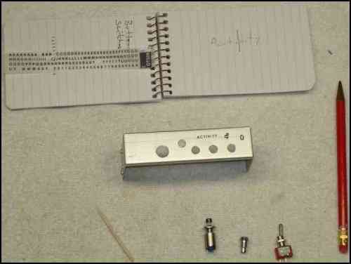
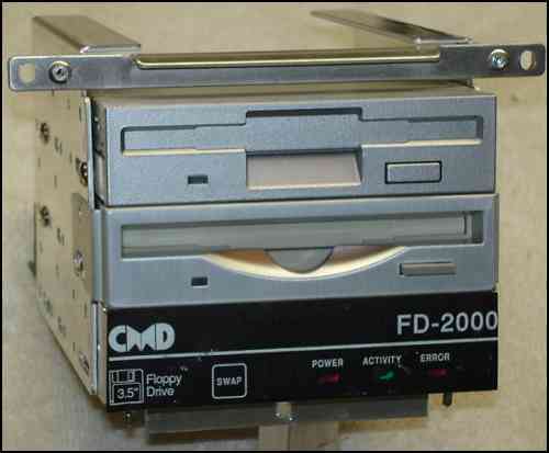
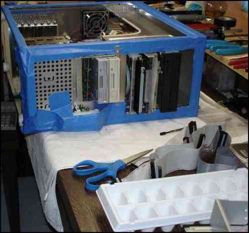
The first plan was to not use the CMD decal at all. Just make small holes for the momentary switch and LEDs.
We would then use decal lettering to label the face plate.
That grew into using replacement switches and LEDs, as seen in the lower right.
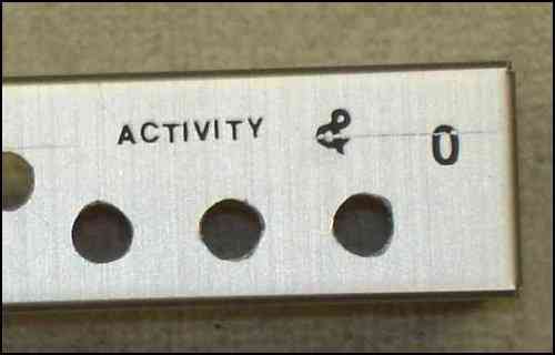
A closeup of the practice lettering. It was not done with the greatest care and better alignment would have been done on the real take.
It was all
too homemade looking and decided to go back to the CMD decal.
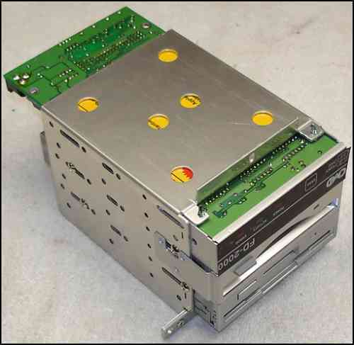
So, it's back to mounting the PCB for the FD 2000.
I cut and folded flat, two tabs for the mounting screws.
That completes the 3.5 bays.
A shot of the face. At this point it is assembled and tested.
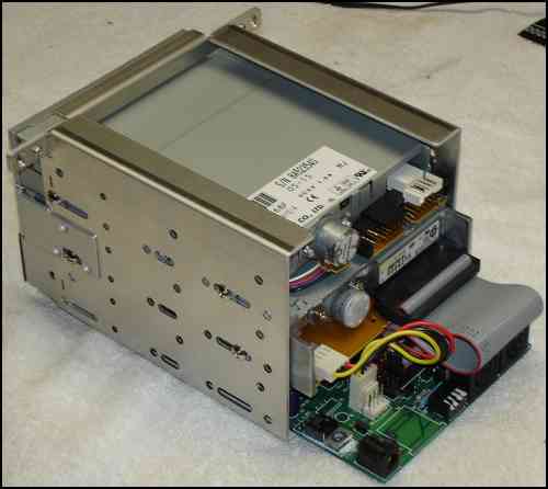
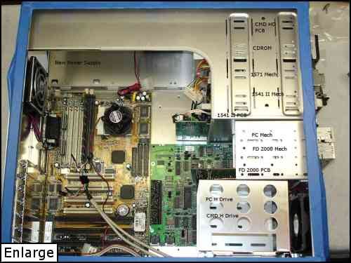
The next step is to locate the remaining pieces.
The PCB for the 1571;
the mechs for the 1571 and 1541 II, and it's PCB;
the
CDROM,
and the CMD HD PCB and drive.
Here you see the placement of the 1571 PCB next to the motherboard. It was the hardest to locate because of it's
size.
A view from the front. This shot is from the early stages of planning and it will change slightly. The FD 2000 PCB is not yet mounted, neither is the
face plate.
A shot of the layout from the inside. The PCB for the CMD HD and the CDROM will be swapped in the final version.